
ENGINEERING RESOURCES / OEM DECISION GUIDE
Axial flux motor DC bus voltage selection
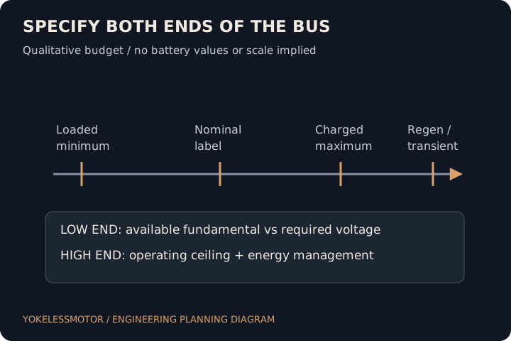
Choose an axial flux motor DC bus window from the voltage at the inverter terminals under load and regeneration. A nominal 48 V or 96 V label leaves both ends unresolved.
By YokelessMotor · Published · Reviewed
THE ENGINEERING DECISION
Check two ends independently: minimum loaded voltage must support the required torque-speed duty with the selected winding and inverter, while maximum charging or regenerative voltage must remain within agreed operating limits. Then reconcile DC input current with the separate phase-current limit.
See method and primary sourcesSpecify a window
Measure the loaded minimum and credible maximum at the inverter terminals.
State current conventions
DC average, phase RMS and phase peak are different quantities.
Reserve voltage headroom
Back EMF, winding drops, modulation and regeneration need separate checks.
1. Specify voltage where the inverter sees it
For each required duty point, record the lowest voltage at the inverter DC terminals after source sag and distribution losses. Separately record the largest voltage expected during charging, braking or a source transition. Include state of charge, source temperature, ageing assumptions and measurement location in the project record.
The table is an original budget template. No cell chemistry or series count is implied by “48 V” or “96 V.” Values remain open until the source and inverter owners agree the actual limits. A maximum component rating is not a target operating setpoint.
| Budget item | Required project input | Decision check |
|---|---|---|
| Minimum source under load | Lowest source terminal voltage at required duty | Include cold / aged source assumptions where applicable |
| Distribution drop | Cables, connectors, contactors and fuses at current / temperature | Subtract from source voltage to obtain inverter-terminal minimum |
| Motor-side requirement | Winding, speed, torque, control mode and voltage convention | Check against available inverter fundamental voltage |
| Maximum charged source | Highest permitted charging voltage and tolerance | Compare with inverter operating ceiling |
| Regeneration / transients | Energy absorption, protective limits and measured excursion | Confirm ceiling and protection with source / drive owners |
2. Calculate a first DC current estimate
For a motoring steady-state screen, IDC ≈ Pshaft / (VDC × ηmotor × ηinverter). This assumes the stated efficiencies at that operating point, excludes auxiliaries and uses average DC quantities. A complete source budget must add auxiliary loads and account for actual loss maps, source ripple and transient behaviour.
Hypothetical comparison: delivering 10 kW at the shaft with an assumed combined motor-and-inverter efficiency of 0.90 needs approximately 231.5 A at 48 V or 115.7 A at 96 V. At loaded values of 40 V and 80 V, the same assumptions give 277.8 A and 138.9 A. These are arithmetic scenarios, not ratings for our low-voltage programme.
| Assumed inverter DC voltage | Calculated average DC current | Interpretation |
|---|---|---|
| 48 V | 231.5 A | Nominal-voltage screen only |
| 40 V | 277.8 A | Lower voltage raises required input current |
| 96 V | 115.7 A | Half the current of the 48 V scenario at equal assumptions |
| 80 V | 138.9 A | Loaded-voltage screen for a different hypothetical source |
3. Separate DC current from phase-current limits
DC input current follows the input power balance. Motor phase current follows torque production, winding constants, speed and control. A battery current calculation therefore cannot be copied into a phase RMS current field. Near zero speed, high holding torque can coexist with low mechanical power and significant winding heating.
EMRAX documents winding-dependent torque constants in Nm per phase RMS ampere. That illustrates why a constant must carry its convention. For a balanced sine wave, phase peak equals sqrt(2) times phase RMS; this waveform identity is not a DC-to-phase conversion. Delta versus star and controller reporting conventions need explicit agreement.
| Quantity | What it describes | Do not substitute |
|---|---|---|
| Average DC input current | Source-side power requirement in the stated condition | Phase RMS current |
| Phase RMS current | Heating-related winding / line quantity, with connection defined | DC current or unlabeled controller current |
| Phase sine peak current | Instantaneous sine amplitude, sqrt(2) × RMS | General waveform peak or a battery limit |
| Torque-current constant | Specified torque per stated current convention | A value from another winding or control convention |
4. Budget motor-side voltage at the loaded minimum
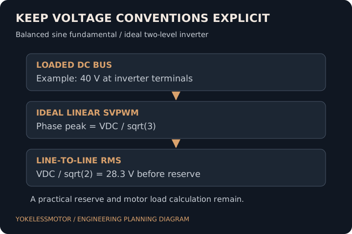
Texas Instruments BPRA073, section 5.3, explains the ideal space-vector modulation voltage boundary. For a balanced sinusoidal fundamental from an ideal two-level inverter in linear SVPWM, the maximum phase-to-neutral peak is VDC / sqrt(3). Converting conventions gives line-to-line RMS VLL ≈ VDC / sqrt(2). These are fundamental values, not PWM switch-node peaks.
At a hypothetical 40 V loaded bus, the ideal ceiling is about 28.3 V line-to-line RMS. Reserving an illustrative 10% of that voltage leaves about 25.5 V for a preliminary comparison. Ten percent is our example assumption, not a recommended universal margin; real dead time, switching drops, current regulation and modulation strategy must be reviewed with the drive supplier.
Compare that available voltage with the required terminal voltage at load, not only open-circuit back EMF. Resistance and inductive terms are vectors and cannot generally be added as scalar magnitudes. Request the winding parameters, temperature, electrical frequency and motor-drive operating calculation. Field weakening is a separate validated operating mode with current, thermal and magnet limits.
- State phase or line-to-line, peak or RMS, fundamental or PWM waveform.
- Calculate with the lowest inverter-terminal bus voltage.
- Obtain the loaded motor terminal-voltage requirement for the specified control mode.
- Agree practical headroom and verify the demanded point without unintended saturation.
5. Close the upper window during regeneration
Kollmorgen explains that deceleration can return energy to a drive bus and cause overvoltage if the system cannot absorb it. A charged battery, a source that cannot sink current or a protection disconnect can change the available energy path. Confirm the source and drive behaviour together rather than selecting the inverter only from nominal voltage.
For the procurement record, identify normal operating ceiling, warning and trip settings, component limits and credible transients separately. A braking resistor or other energy path must be compatible with the actual drive and application; this guide does not size one. Regenerative braking also does not establish a complete vehicle or machine stopping function.
| Condition | Question for the system owner | Evidence to request |
|---|---|---|
| Full-charge braking | Can the source accept the requested charging current? | Source acceptance envelope and drive limiting strategy |
| Non-sinking bench supply | Where does returned energy go? | Compatible bus-energy management and measured ceiling |
| Source disconnect / fault | What does the drive do while the load is moving? | Defined protection response and system-level validation |
| Transient excursion | How much headroom remains at the measured terminals? | Waveform, measurement bandwidth and approved limits |
6. Decide what a move from 48 V to 96 V resolves
For unchanged transmitted DC power and the same conductor resistance, doubling bus voltage halves average DC current and quarters the corresponding DC I²R loss. This arithmetic applies to that distribution path. It does not prove that a rewound motor has one-quarter of the winding loss or that its continuous output doubles.
Two hypothetical paths need different evidence. An existing 48 V machine with fixed protection and cable interfaces should first resolve its loaded voltage and current bottleneck. A new 96 V architecture can be compared at system level, including source, inverter, insulation, connectors, protection and service requirements. Neither is automatically cheaper or suitable for every application.
| Programme | First decision | Do not infer |
|---|---|---|
| Existing 48 V system; high current concern | Measure loaded bus and distribution losses before changing the winding | That a higher-voltage motor can use the existing drive |
| New 96 V concept; package still open | Compare complete electrical architectures and duty evidence | That lower DC current alone proves a thermal or safety result |
7. Send a bus budget with your motor enquiry
Keep unknowns explicit in the worksheet. The motor supplier needs the actual duty points and motor-side current convention; the drive supplier needs the winding and feedback interface; the source owner needs motoring and regenerative limits. Assign someone to reconcile the complete record.
A feasibility reply should identify which point is constrained by bus voltage, current, speed or thermal capability and which inputs still need measurement. A generic “48 V compatible” reply is insufficient for releasing a system interface.
- Source nominal / loaded minimum / charging maximum at the inverter terminals.
- Torque, rpm, continuous time, peak duration and repetition.
- DC current and phase-current limits with RMS / peak conventions.
- Winding, back-EMF convention, drive, position feedback and control mode.
- Cooling, regenerative energy path, quantities and test acceptance owner.
8. Method, assumptions and unresolved inputs
Reviewed on 21 October 2026. The primary documents support winding/current conventions, ideal modulation and bus-energy behaviour. All numerical bus and current examples are our hypothetical arithmetic. They are not battery designs, motor ratings, tested efficiency or electrical safety approvals.
This is a cross-platform interface guide, not another 48 V or 96 V product page. The next gate requires actual source limits, drive documentation, winding data and an agreed test of the demanded operating points. The examples exclude auxiliaries and dynamic source behaviour unless explicitly stated.
- Integrator: own the complete minimum / maximum voltage budget.
- Motor and drive suppliers: reconcile conventions and achievable duty.
- Verification team: measure the agreed worst-case operating points.
SELECTION QUESTIONS
Questions engineers ask.
Is nominal 48 V enough to select an inverter?
No. Specify loaded minimum, maximum charged voltage and credible regenerative or transient excursions at its DC terminals.
Does a 96 V system need half the current?
For equal DC input power, doubling voltage halves average DC current. Motor phase current and complete-system losses need a separate winding and control calculation.
How much DC current does a 10 kW motor need?
It depends on shaft output, loaded bus and efficiency. At an assumed 90% combined efficiency, 10 kW shaft output at 48 V requires about 231.5 A average DC, excluding auxiliaries.
Can I use battery current as phase RMS current?
No. They describe different sides of the inverter. Use the motor and drive conventions and the actual torque-speed operating point.
When can peak current be converted with sqrt(2)?
For the same sinusoidal phase waveform, peak equals sqrt(2) times RMS. This is not a conversion between DC input and phase current or between arbitrary waveforms.
Is motor AC voltage equal to DC bus voltage?
No. In an ideal two-level inverter with balanced sinusoidal fundamental and linear SVPWM, maximum line-to-line RMS is VDC divided by sqrt(2). Practical voltage availability is lower or otherwise constrained by the drive.
Is ten percent voltage reserve sufficient?
The ten-percent value is only a worked assumption. Agree the required reserve with the drive supplier using modulation, switching effects, control and measurement evidence.
Does back EMF alone determine the minimum bus?
No. The loaded terminal-voltage requirement also involves winding impedance, electrical frequency and control. Confirm the voltage convention before comparing values.
Can field weakening fix every voltage shortfall?
No. It changes the operating mode and may introduce additional current, thermal and magnet constraints. It needs specific motor-drive evidence.
Why does braking affect the maximum bus voltage?
Returned energy can raise the DC bus when the source cannot absorb it. Agree the compatible energy path, current limits and protection response.
Does higher voltage quarter motor copper loss?
That conclusion is unsupported. Quarter loss applies to an unchanged DC path resistance when current halves; a different winding and operating point need their own loss calculation.
What is the next step after the worksheet?
Resolve unknown source and drive limits, obtain winding conventions, and agree a motor-drive calculation and verification plan for the required duty.
Primary sources and review scope.
Sources checked on 21 October 2026. External manufacturer descriptions apply to their own products. The analysis, decision tables and hypothetical examples in this guide do not constitute a YokelessMotor test report or a certification claim.
- EMRAX 228 datasheet V1.7, table on PDF page 2
Example of explicitly timed S2 output, S1 output, cooling-dependent columns and winding variants. Applies to this manufacturer and revision only; not our specifications.
- Texas Instruments BPRA073, section 5.3 / Figure 13
Foundational February 1998 application note: ideal linear space-vector voltage boundary. RMS conversion and numerical screening here are our derivations; this is not a current product recommendation.
- Kollmorgen: regenerative resistor function and sizing scope
Returned bus energy, possible overvoltage and the need for compatible sizing. No resistor or drive is selected in this guide.
TURN THE COMPARISON INTO A BRIEF
Bring the constraints that matter.
Start with non-confidential duty, package, quantities and acceptance requirements. Request an NDA before detailed drawings. The next step is a scoped feasibility discussion.
Discuss a voltage and current brief