
DECISION / 01
Close the mass boundary
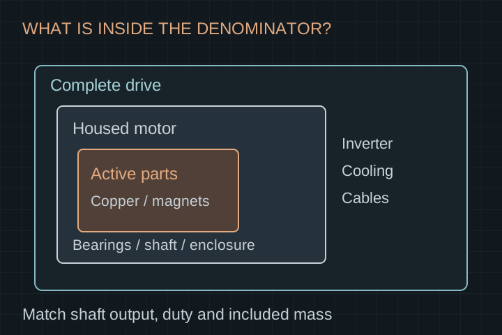
Request separate active-parts, assembled-motor and installed-drive mass budgets. Include the cooling hardware assigned to each propulsion unit and identify shared equipment.
APPLICATION ENGINEERING / OEM & R&D
Bring the mission profile before the power-density target. Review a rotor, stator or motor development scope against installed mass, cooling and propulsion interfaces.
Component, assembly or custom motor scope · Reviewed 20 October 2026
START WITH THE CONSTRAINTS
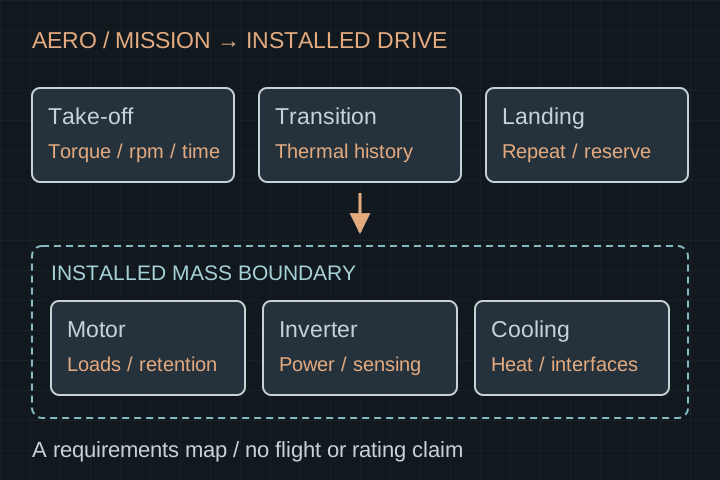
A lightweight active stack can become a heavier installed propulsion unit after bearings, retention, cooling, inverter, cables and mounts are included. Repeated take-off, transition and landing loads also depend on the preceding thermal state. Evaluate the motor inside the aircraft team’s mission and installation model.
DECISION / 01
Request separate active-parts, assembled-motor and installed-drive mass budgets. Include the cooling hardware assigned to each propulsion unit and identify shared equipment.
DECISION / 02
Record torque, speed, duration, repetition and starting temperature for each mission segment. Add the program-defined contingency cases instead of reusing a headline peak number.
DECISION / 03
Provide propeller thrust, radial loads, overturning moments and vibration inputs. For a frameless kit, assign bearings, retention, alignment and final air-gap verification explicitly.
REQUIREMENT → EVIDENCE
Use this proposed review matrix to identify what is known, what needs a test and who can approve the result. Acceptance limits are agreed for your project.
| Decision | Input to provide | Evidence to agree |
|---|---|---|
| Mission duty | Torque / rpm / seconds for each segment; repetition and contingency cases | Time-aligned electrical, shaft-output and temperature records |
| Battery and inverter | DC window, current limits, switching strategy, feedback and fault interfaces | Motor–inverter operating envelope at agreed bus and thermal conditions |
| Cooling and altitude | Ambient conditions, installation airflow or coolant inlet / flow / pressure budget | Thermal test boundary and derating review for the intended installation |
| Installed mass | Included motor, inverter, cables, mounts and allocated cooling hardware | Itemized mass statement; no active-stack versus full-system comparison |
| Propulsor loads | Axial / radial loads, moments, speed range and vibration spectrum | Bearing, rotor retention and hot-clearance verification plan |
| Program release | Intended aircraft, development stage and designated approval parties | Agreed qualification matrix and ownership of unresolved evidence |
Assume a 60 kW shaft-output target, a 6 kg motor and another 4 kg allocated to inverter, cables, mounts and cooling. The motor-only ratio is 60 / 6 = 10 kW/kg; the defined installed-drive ratio is 60 / (6 + 4) = 6 kW/kg.
These are hypothetical budget figures, not our motor data. Both ratios also need the same duty duration and thermal conditions before they support a design decision.
SUPPLY AND INTEGRATION
| Work package | Proposed supply scope | Aircraft / integration team |
|---|---|---|
| Component or motor prototype | Agreed drawing revision, manufacturing review and sample inspection records | Mission inputs, interface drawings and acceptance approval |
| Motor–inverter evaluation | Motor parameters and agreed bench-test participation | Selected inverter, controls integration and system protection owner |
| Propulsion installation | Defined shaft, mounting, retention and cooling interfaces | Propeller integration, aircraft structure, installation loads and aircraft-level assessment |
| Qualification and release | Only the tests and records explicitly commissioned | Qualification basis, independent evidence review and flight-release decisions |
REVIEW / 01
Revision-controlled mission table, mass boundary and list of missing load cases.
REVIEW / 02
Bench configuration, sensors, test limits and handling of abnormal results.
REVIEW / 03
Program owner reviews prototype evidence against installation and qualification requirements.
This is a development procurement route. Flight qualification, fault tolerance and aircraft approval require a separately agreed program and evidence; no airworthiness certification or flight-ready product is stated.
Review air-gap and inspection planningFIRST CONVERSATION / NON-CONFIDENTIAL
Your inquiry opens the requirements discussion. We first identify missing inputs and the requested deliverables; feasibility, price, schedule and verification work need a project-specific agreement.
The contact form carries this application and source page. Request an NDA before sharing proprietary drawings. It records requirements and does not upload CAD or execute an agreement.
Discuss an aero development scope Download the application worksheetReview battery current and cooling for a low-voltage architecture.
Review low-voltage motor developmentReview insulation, controls and thermal interfaces for the chosen bus.
Review high-voltage propulsion developmentScope rotor materials, retention and drawing-led assembly work.
Review magnet rotor assembliesNo flight-certified model is offered on this page. Start with the intended aircraft, development stage, scope and qualification owner. Any commissioned prototype and evidence package must be defined before a separate release decision.
Yes, a component feasibility review can be scoped independently of a complete motor. Agree drawing authority, manufacturing interfaces, inspection and responsibility for the final rotating assembly.
No. Define output duration, thermal conditions and included mass first. The arithmetic example on this page illustrates a comparison boundary and is not a validated motor specification.
That depends on losses, installation airflow, ambient conditions and time at load. Supply the actual cooling boundary and preceding thermal state; propeller operation alone does not establish the motor’s available cooling.
The scope must name that owner. A component or frameless quotation does not automatically include bearings, propeller support, shaft-load verification or final air-gap control.
Send a non-confidential mission summary, envelope, bus window, cooling concept and scope. Select the NDA request in the inquiry form before sharing proprietary geometry. The request does not execute an agreement.
Reviewed by the YokelessMotor editorial team on 20 October 2026. Tables, examples and responsibility splits are our proposed planning tools. External sources provide context, not evidence of our tested hardware or certification.
System-boundary context: an EHPS can include motors, power distribution, cooling and controls. This is not a determination of the requirements applicable to your aircraft.
Sections 3.2, 3.3 and 3.6 illustrate manufacturer-specific mounting, output and cooling conditions. EMRAX limits do not establish ratings for our development scopes.