CUSTOM MOTOR DEVELOPMENT / OEM & R&D

High-voltage axial propulsion. Define the system boundary.

Up to 800 V DC / 50–200 kW inquiry targets

Review a compact propulsion package around continuous shaft output, the actual DC voltage window and the available cooling loop. Define motor, inverter and integration responsibilities before turning a target power into a prototype specification.

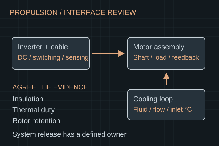
Propulsion review showing motor and inverter interfaces, a separate coolant loop and a list of insulation, feedback and mechanical acceptance boundaries
Integration concept for a custom program. Voltage and power bands are inquiry targets, not verified ratings, a released product or a certified propulsion system.

THE PROGRAM STARTS HERE

Resolve the constraints that change the design.

01

Insulation as a complete interface

Document maximum DC voltage, inverter switching conditions, cable length, winding-to-frame requirements, grounding and the environment. Agree insulation test methods and limits for the specific assembly rather than copying a generic voltage label.

02

Cooling with operating conditions

Compare jacket, stator-contact or direct-fluid concepts against the heat path, coolant compatibility, pressure drop, sealing and maintenance requirements. Oil and water-based loops have different electrical and material interfaces.

03

Propulsion loads beyond torque

Include thrust, gyroscopic and maneuver loads, overspeed conditions, shaft coupling and rotor containment responsibilities. An electromagnetic design is one part of the mechanical release.

INPUTS / INTERFACES / OWNERSHIP

Build a usable operating envelope.

These are the decisions to scope before a quotation. Feasibility, engineering deliverables, sample cost, tooling and recurring production terms follow the agreed requirements.

High-voltage propulsion interface review
InterfaceCustomer inputsAcceptance boundary
Bus & inverterMinimum / nominal / maximum DC voltage; drive and switching dataBack-EMF, field-weakening assumptions, current and speed limits
InsulationOperating environment, grounding, cable and insulation requirementsAgreed resistance / withstand methods and any partial-discharge investigation
ThermalOutput cycle, coolant type, inlet temperature, flow and pressureStabilized continuous output, peak duration and measured temperatures
Rotor mechanicsMaximum operating / transient speed, thrust and radial loadsRetention, balancing, clearance and agreed overspeed evidence
ControlsInverter, resolver / encoder, communications and fault strategySignal compatibility, commissioning and fault-response responsibilities
Program releaseApplication, market, validation owner and evidence packagePrototype acceptance distinct from vehicle, marine or flight approval

WORKED EXAMPLE / ASSUMED INPUTS

100 kW is incomplete without speed

For an illustrative 100 kW shaft operating point, torque is about 318 Nm at 3,000 rpm, or about 159 Nm at 6,000 rpm. Both points have the same mechanical power and very different design implications.

T (Nm) = 9550 × P_shaft (kW) / n (rpm)

This is a rounded unit conversion, not an available torque–speed curve. Continuous output also needs the heat rejection, winding limits and test conditions. The two points are not asserted to lie on one motor envelope.

Download motor brief worksheet

APPLICATION-SPECIFIC DUTY

Bring the load case behind the power number.

EV & motorsport development

Review the full traction cycle, gearing, regeneration, inverter mapping and hot restart. Compare packaged drive mass and cooling auxiliaries alongside motor-only numbers.

Marine propulsion

Sustained duty, shaft loads, coolant fouling, corrosion and maintenance access can dominate. Identify the integrator and any vessel-specific acceptance requirements.

Aviation propulsion research

Provide altitude and ambient envelopes, thrust loads, mission duty and cooling-fault scenarios. No airworthiness, redundancy or flight-use approval is implied by an engineering discussion.

AGREE ACCEPTANCE BEFORE SAMPLES

Request the evidence for your operating point.

  • A controlled drawing and interface pack defining shaft, mounting, coolant, electrical and feedback connections.
  • Torque–speed and efficiency evidence with test voltage, current conventions and measurement boundary.
  • Thermal records stating coolant inlet, flow, ambient, peak timing and winding / magnet temperature methods.
  • An agreed insulation, retention, balance, overspeed and fault-investigation scope.
  • Clear ownership of inverter tuning and system validation; application approval remains separately defined.
Review inspection and release gates
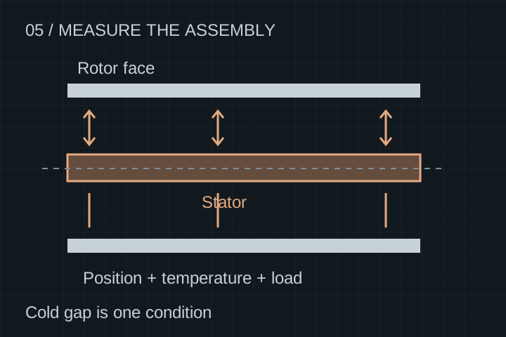
Separate rotor-to-stator clearances measured across an assembly at defined positions
Cold component dimensions do not establish hot, loaded assembly clearance. Agree the build, conditions, inspection methods and release owner.

START WITH A NON-CONFIDENTIAL BRIEF

Discuss your high-voltage propulsion programs.

Send the requirements and quantities first. Request an NDA before sharing detailed proprietary CAD. The review defines feasibility, deliverables and responsibilities before pricing or timing is confirmed.

  • DC voltage window and intended inverter data
  • Shaft torque–speed duty cycle and peak timing
  • Package, mass boundary, thrust and bearing loads
  • Coolant specification, temperature, flow and pressure budget
  • Prototype quantity, validation scope and target production plan

Start your engineering brief.

Use the inquiry form, or contact us directly with your duty cycle, package, cooling and quantity requirements.

ENGINEERING & PROCUREMENT

Questions before a motor RFQ.

Is this an 800 V, 200 kW rated product?

No released model is represented here. Up to 800 V and 50–200 kW describe the inquiry envelope. A specific operating point, continuous output and insulation design require feasibility review and agreed verification.

Can this replace a YASA P400 or P750 directly?

No direct replacement or parameter equivalence is claimed. Share the actual mounting, electrical, cooling and duty requirements for an independent design review. YokelessMotor is not affiliated with YASA or Mercedes-Benz.

Should I choose direct oil cooling or a water jacket?

Choose through a system thermal and materials review. Heat path, fluid compatibility, sealing, pumping, contamination and service requirements matter. No cooling method guarantees a particular continuous rating by itself.

Is the program certified for automotive or flight use?

No such certification is stated. Define the applicable program requirements, qualification evidence and responsible approval parties before commissioning hardware for a regulated application.

Will a peak power number define the continuous motor size?

No. Peak duration, starting temperature, recovery time, coolant conditions and torque–speed duty are required. Continuous output must be tied to a defined thermal test rather than a fixed fraction of peak.

Can I start with components rather than a complete motor?

Yes. Specify the stator, rotor or housing deliverable and the interfaces you retain. Component inspection and the final propulsion-system release are separate acceptance activities.

Continue your engineering review.

Engineering resources and selection guides

Connect this scope to your application.