
01
Battery window before nominal voltage
Specify minimum loaded voltage, nominal voltage and maximum charged voltage, plus regeneration limits. A label of 48 V alone does not define the inverter voltage class or available loaded speed.
CUSTOM MOTOR DEVELOPMENT / OEM & R&D
48–96 V DC / 5–30 kW inquiry targets
For OEM teams developing mobile machinery, compact vehicles, heavy UAVs or marine prototypes, a thin motor package is only one constraint. Bring the battery window, load cycle and cooling budget together before choosing a winding or inverter.
THE PROGRAM STARTS HERE
01
Specify minimum loaded voltage, nominal voltage and maximum charged voltage, plus regeneration limits. A label of 48 V alone does not define the inverter voltage class or available loaded speed.
02
State the torque–speed points and time at each point, including starting, hill holding, take-off or bollard pull. Agree peak duration, initial temperature and recovery time separately.
03
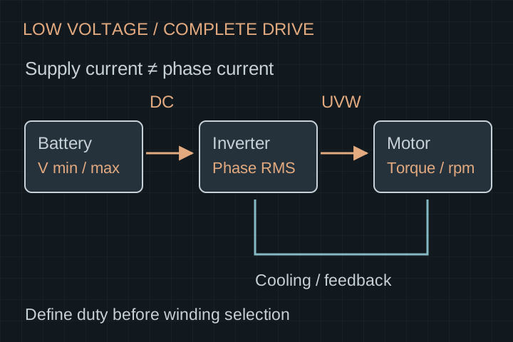
Review phase current, back-EMF, pole pairs, position feedback and the intended control method with the inverter supplier. Motor, cable, connector and battery current limits belong in the same review.
INPUTS / INTERFACES / OWNERSHIP
These are the decisions to scope before a quotation. Feasibility, engineering deliverables, sample cost, tooling and recurring production terms follow the agreed requirements.
| Input | What to provide | What the review resolves |
|---|---|---|
| DC supply | Minimum / nominal / maximum voltage under load | Winding and inverter operating window; regeneration headroom |
| Mechanical output | Continuous and timed peak torque at stated rpm | Electromagnetic loading and thermal duty; no rating inferred from kW alone |
| Current budget | Battery DC limit and inverter phase RMS / peak limits | Separate supply, winding, interconnect and drive constraints |
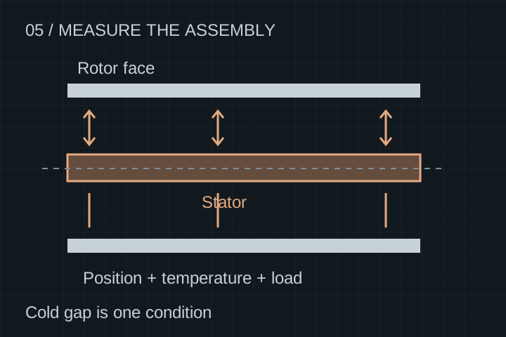
| Package | Outer diameter, axial length, shaft, mounting and load direction | Housed motor versus frameless kit; bearing and integration ownership |
| Cooling | Airflow or liquid type, inlet temperature, flow and pressure budget | Heat path and test boundary; auxiliary cooling hardware scope |
| Environment | Ambient, vibration, contamination, splash and corrosion exposure | Protection requirements and a project-specific verification plan |
WORKED EXAMPLE / ASSUMED INPUTS
Illustrative calculation only: assume 10 kW shaft output and 90% combined motor-and-inverter efficiency at that operating point. Required DC input is about 11.11 kW. At a loaded 48 V the average supply current is about 231 A; at 96 V it is about 116 A.
I_DC = P_shaft / (η_drive × V_DC)
The 90% value is an assumed example, not measured performance. These are average DC currents, not phase RMS currents. Voltage sag, ripple, transients and thermal limits still require a drive review.
APPLICATION-SPECIFIC DUTY
Bring wheel force, reduction ratio, starts per hour, stall or holding periods and ambient temperature. Repeated low-speed torque can govern the design even when average power is modest.
Separate take-off and cruise points, propeller inertia and thrust loads. Include vibration and loss-of-cooling cases. Any flight qualification remains a separate program with the responsible integrator.
Specify continuous propeller duty, shaft loads, coolant source, salt exposure and enclosure needs. A water-cooled design does not by itself establish immersion or corrosion performance.
AGREE ACCEPTANCE BEFORE SAMPLES
START WITH A NON-CONFIDENTIAL BRIEF
Send the requirements and quantities first. Request an NDA before sharing detailed proprietary CAD. The review defines feasibility, deliverables and responsibilities before pricing or timing is confirmed.
Use the inquiry form, or contact us directly with your duty cycle, package, cooling and quantity requirements.
ENGINEERING & PROCUREMENT
This page opens a custom engineering inquiry. The 5–30 kW band is a target scope, not a catalogue of released models. Availability, price, drawings and delivery dates require a project review.
Possibly within a reviewed operating envelope, but the same torque, speed and continuous output cannot be assumed at both voltages. Winding back-EMF, inverter limits, maximum speed and thermal loading must be checked.
No. DC input current describes supply power; phase current is tied to the winding and torque production. The relationship varies with operating point and switching. Provide both limits with RMS or peak definitions.
Yes, select a kit scope in your project summary. Define who owns bearings, housing, alignment, retention, cooling and final assembled testing before comparing kit and complete-motor quotations.
A drive system can be discussed, but no controller is included by default. Compatibility requires the exact voltage window, current definitions, motor constants, feedback and commissioning responsibilities.
Winding and electromagnetic changes, mechanical tooling, materials, assembly fixtures, test scope, quantity and documentation all affect cost. A quote should separate development, tooling, samples and recurring units.