CORE COMPONENTS / DRAWING-LED REVIEW

Axial flux PCB stators. Review the electrical and thermal stack.

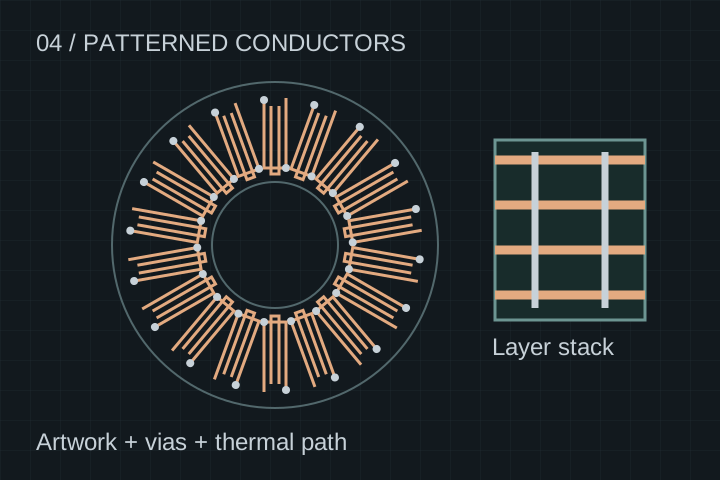
An axial flux PCB stator replaces wound coils with patterned conductors. Bring the winding artwork, layer connections and cooling boundary together before treating a board outline as a motor-ready stator.

OEMs and R&D teams · Components or subassemblies · Scope confirmed after review

Ironless PCB stator concept with radial copper conductor paths, interlayer vias and a separate layer stack illustration
Conceptual conductors and layer stack. This is not Gerber artwork, a verified winding pattern or a current-rated board.

DESIGN TO MANUFACTURING

A reproducible trace pattern still needs a credible heat path.

Copper thickness, trace width, vias and terminations set electrical and manufacturing constraints. Laminate choice and cooling determine a separate thermal boundary. Removing stator iron does not remove copper loss, rotor loss, torque ripple or the need for system validation.

01

Keep topology boundaries clear

A PCB stator is an adjacent ironless architecture, distinct from a yokeless segmented iron-cored stator. Assess torque, voltage, loss and packaging against your application rather than assuming an interchangeable replacement.
02

Review the complete fabrication package

Supply layer artwork, stack-up, netlist, drill files and terminal details. Discuss copper thickness, clearances, registration and via construction before locking the winding geometry.

03

Define test access early

Provide phase identification and accessible test points. Agree continuity, resistance measurement temperature and isolation requirements so electrical acceptance is possible before integration.

DFM / SCOPE & COST DRIVERS

From winding artwork to a reviewable PCB stator brief.

Use these decisions to scope a prototype. No board current rating, efficiency or motor torque is implied by this matrix.

From winding artwork to a reviewable PCB stator brief.
DecisionRequired inputTrade-off to review
ConductorsTrace artwork, copper specification, current waveform and resistance target.Copper loss, manufacturable feature spacing and etching/stack-up limits.
Interlayer connectionsWinding netlist, via/drill definitions and phase terminations.Connection resistance, thermal paths, inspection access and joint construction.
Insulation stackBus/phase voltage, transients, laminate and insulation requirements.Spacing, dielectric test conditions, temperature and environmental exposure.
Mechanical integrationActive annulus, mounting, flatness and assembled clearance budget.Board support, thermal expansion, warpage and rotor clearance.
Cost and revisionPrototype quantity, layer count, panel constraints and expected redesigns.Setup/NRE, board fabrication, termination, inspection and repeat-order cost.

AGREE THE EVIDENCE

Define acceptance before samples.

  • Confirm artwork, stack-up and material revisions before fabrication.
  • Agree inspection of conductors, layer registration, vias and critical thicknesses.
  • Specify continuity, phase resistance and isolation test conditions.
  • Separate board acceptance from motor torque, thermal and endurance validation.

No stock PCB stator, flight-qualified unit, certified medical part or current rating is offered on this page. Fabrication feasibility, materials, quantities and validation scope require a project review. Do not send restricted artwork before confidentiality terms are agreed.

Air-gap metrology & quality gates
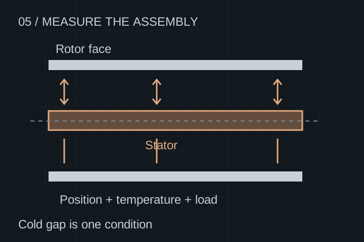
Conceptual inspection of both rotor-to-stator gaps at several positions, with temperature and load as separate conditions
Component results and assembled clearance are separate records. Test method, equipment, conditions and release responsibility are agreed per project.

START WITH NON-CONFIDENTIAL INPUTS

Prepare your PCB brief.

Send the scope and operating envelope first. Request an NDA before sharing proprietary artwork or detailed CAD. The next step is scope clarification and feasibility review; pricing and timing follow the agreed deliverable.

  • Gerber or agreed PCB fabrication format, drill files, netlist and controlled stack-up.
  • Phase connection diagram, copper/laminate specifications and terminal drawing.
  • Voltage/transients, current waveform, speed/frequency and thermal boundary.
  • Mechanical envelope, mounting/clearance requirements and electrical acceptance plan.
Engineering inquiry details
Operating envelope (optional)

Enter target continuous values in the stated units. Describe peak duration, duty cycle and temperature limits in your summary. These inputs are requirements, not a product rating.

Selecting a request does not sign an NDA or confirm material availability or export clearance. We review the actual part, destination and documentation needs.

Email directlyWhatsApp this brief

If the form is unavailable, contact [email protected] or WhatsApp +8618857971991.

ENGINEERING FAQ

Before a pcb quotation.

Is a PCB stator the same as a segmented yokeless stator?

No. A PCB stator uses patterned conductors and can be an ironless architecture. A segmented yokeless stator may retain magnetic teeth. They require different electromagnetic, thermal and manufacturing reviews.

Does an ironless PCB stator guarantee zero torque ripple?

No. Removing stator teeth removes that source of cogging, but torque ripple, magnet geometry, current waveform and control still need system-level review. No zero-ripple motor performance is claimed here.

What current can the board carry?

There is no universal rating. Share the copper and via geometry, current waveform, cooling, temperature limits and duty cycle. Establish acceptance through analysis and tests on the actual stack and assembly.

Can you manufacture directly from an outline drawing?

An outline can start a discussion. Fabrication needs controlled conductor artwork, layer stack, drill data, connections, materials and inspection requirements. Electromagnetic design ownership must also be agreed.

RELATED COMPONENTS

Review the mating interfaces.

Architecture background: patterned copper can replace conventional windings in a PCB stator. Infinitum’s designs, results and intellectual property are their own; no affiliation or equivalent performance is implied. Infinitum: PCB stator technology overview.

Published / reviewed 20 October 2026 · YokelessMotor engineering content · Illustrations and planning guidance, not measured production results. About the project.

Request your component review