
ENGINEERING RESOURCES / OEM DECISION GUIDE
SMC vs laminated steel for axial stators
Choose the core material and manufacturing route together. Compare flux paths, losses and tooling.
By YokelessMotor · Published and reviewed
THE ENGINEERING DECISION
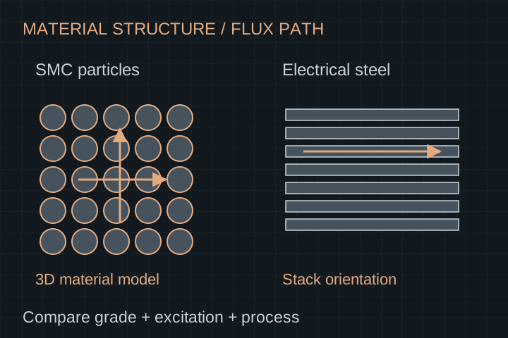
Shortlist SMC where a three-dimensional flux path and net-shaped segmented tooth offer useful design freedom. Keep a suitable electrical-steel construction in the comparison where flux orientation, loss behavior and the production route fit. Choose specific grades and finished processes with matched B–H and loss data; “SMC versus steel” alone cannot identify the better stator.
See method and primary sources1. Start with the actual flux path
SMC uses insulated soft-magnetic particles compacted into a component. Höganäs describes its Somaloy materials as having three-dimensional magnetic properties and net-shaping possibilities. A laminated construction instead assembles insulated electrical-steel layers; the intended flux orientation must be designed with that stack.
An axial air-gap flux direction does not mean every part of the stator has the same flux direction. Examine the tooth, tip and any return path. A label such as “segmented stator” does not decide the material or make a conventional radial lamination layout suitable without review.
| Dimension | SMC component | Laminated electrical steel |
|---|---|---|
| Structure | Insulated magnetic particles in a compacted shape | Insulated sheets assembled in a controlled orientation |
| Magnetic model | Grade, achieved density and processing condition | Grade, thickness, direction and stack construction |
| Shape decision | Compaction access, ejection and component support | Cutting or winding route, stacking, joining and access |
| First evidence request | B–H / loss data and finished-part process conditions | B–H / loss data and cut / assembled stack conditions |
2. Translate speed into a material test question
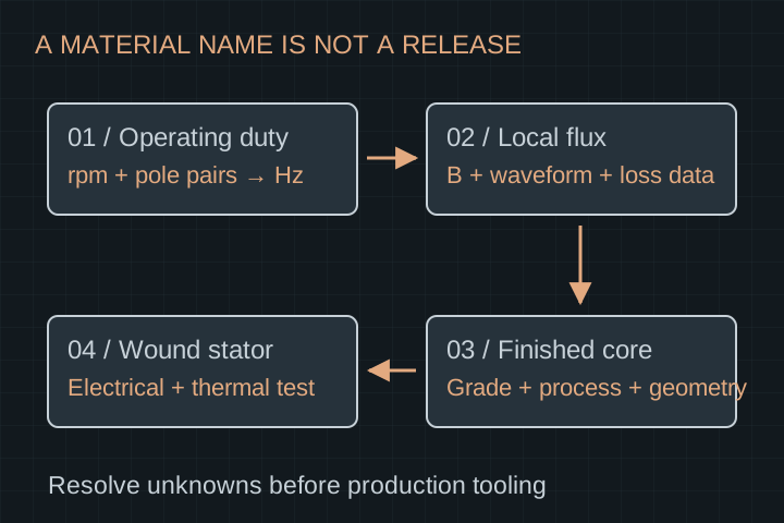
For a synchronous PM design, fundamental electrical frequency is f = p × n / 60, where p is pole pairs and n is rpm. An illustrative 10-pole-pair motor at 3,000 rpm has a 500 Hz fundamental. This is arithmetic for a hypothetical design, not a rating or loss prediction.
The loss request still needs local flux density, waveform and temperature. PWM and spatial harmonics can add excitation beyond the fundamental. Do not select a material from a 50 Hz data point simply because its headline loss is lower. Compare the candidate grades at the application’s relevant conditions.
- List pole pairs and the complete speed range.
- Request local flux-density estimates for each critical region.
- State fundamental frequency and relevant harmonic / PWM assumptions.
- Use material data valid for the intended waveform and temperature range.
3. Avoid the datasheet test-method trap
Höganäs explicitly distinguishes its SMC ring-component measurement from electrical-sheet data commonly measured with an Epstein frame. Its material sheet warns that the values are not directly comparable without accounting for the specimen and method. Record that difference before building a winner/loser table.
Ask both suppliers for the test specimen, grade, processing, frequency, flux density, waveform and loss definition. If the methods cannot be reconciled, treat a numerical ranking as unresolved and request a comparable finished-core evaluation. Do not draw a crossover curve from unmatched data points.
The tradeoff is not “powder has no losses.” A Höganäs-authored technical paper explains that insulation between particles restricts eddy currents, while relatively high hysteresis loss has limited SMC use compared with Fe–Si laminates. That material-family observation does not choose a grade for this motor: the total loss at its actual excitation and processed geometry still decides.
| Field | Record explicitly | Why it matters |
|---|---|---|
| Specimen and method | Ring component, sheet, stack or finished core; test method | Different specimen and processing effects can enter the result |
| Excitation | Frequency, peak flux density, waveform and harmonic content | Loss depends on the excitation rather than material name alone |
| Material condition | Grade, density or thickness, heat treatment and temperature | Catalogue and processed-component properties may differ |
| Reported result | Specific loss in W/kg, sample mass and uncertainty | A per-kilogram ranking is not a complete assembled heat balance |
| Motor use | Local flux and core mass distribution | The same specific loss does not imply the same motor loss |
4. Qualify the process with the material
For an SMC tooth, request the specific powder, compaction conditions, achieved density, heat treatment and component verification. The powder trade name alone does not describe the delivered tooth. Geometric features must also be reviewed for pressing, ejection, insulation and assembly support.
For electrical steel, identify fully versus semi-processed material and the intended cutting, stacking and bonding route. voestalpine distinguishes these processing states and the associated annealing requirements. Its grade documentation also describes insulation and bonding systems. Those details need to match the actual manufacturing route.
| Stage | SMC review | Lamination review |
|---|---|---|
| Shaping | Tool access, density distribution, ejection and feature integrity | Cut / punch / wound geometry, edge quality and sheet orientation |
| After shaping | Grade-specific thermal process and coating integrity | Grade-specific annealing decisions and interlayer insulation |
| Joining / support | Tooth support, insulation and assembly stress | Stack joining, bond compatibility and dimensional stability |
| Release sample | Finished geometry, density / material evidence and magnetic checks | Finished stack dimensions, insulation condition and magnetic checks |
5. Include winding and cooling in the stator decision
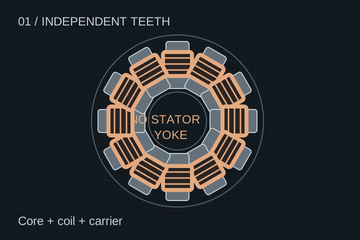
A tooth that looks attractive magnetically can still create difficult coil insertion, insulation, lead routing or potting. Review the winding window, bend limits, fill assumptions and assembly sequence with the exact tooth shape. A core-only quotation leaves these interfaces unresolved.
Thermal qualification must include conductor, insulation, resin, support and the cooling boundary. A bulk material thermal-conductivity value alone does not establish winding temperature. The comparison should include the actual interfaces and build process. This is our integration recommendation, not a published thermal ranking of the two materials.
- Agree wire / foil / Litz choice, turns, connections and revision control.
- Define coil-to-core insulation and assembly clearances.
- Specify resin compatibility, cure process and void / dimensional inspection.
- Validate winding temperature under the agreed load and cooling conditions.
6. Choose the next experiment for your program
The following scenarios are hypothetical procurement decisions. None establishes a default winner. Use the smallest experiment that resolves the largest material or process uncertainty before committing to production tooling.
| Program situation | Useful next step | What it resolves |
|---|---|---|
| Complex three-dimensional tooth; design still changing | Compare SMC forming feasibility with a credible alternative construction | Shape freedom versus tooling and revision constraints |
| Geometry settled; sustained thermal duty dominates | Evaluate matched finished-core losses and an instrumented wound-stator sample | Material / process loss contribution and the actual heat path |
| Low sample volume; recurring volume uncertain | Separate prototype route, dedicated tooling and later production economics | Whether a low initial commitment changes recurring cost or evidence needs |
7. Put a finished-component evidence pack in the RFQ
Ask for a controlled material and process route rather than “SMC or equivalent.” Specify how substitutions are approved and how a material lot relates to the finished component. Agree which checks are performed on every unit and which belong to process qualification.
Cost comparison should separate material, shaping tooling, winding fixtures, insulation, potting, inspection, scrap assumptions and recurring assembly. No universal cost threshold or minimum economic quantity is supported by the sources here. Obtain project-specific quotations.
- Controlled drawing, datums, material grade and revision.
- Material lot and relevant processing records.
- Finished dimensions and agreed magnetic / insulation checks.
- Wound-stator electrical and thermal acceptance conditions.
- Tooling ownership, substitutions, sample release and recurring inspection plan.
8. Method, evidence limits and the decision gate
Reviewed on 20 October 2026. The manufacturer documents below support structure, material-data and processing distinctions. The decision tables and scenarios are our engineering synthesis. No material is claimed to be stocked, qualified or routinely manufactured by YokelessMotor based on these external sources.
We do not have a matched set of grade-specific processed-core tests for your geometry. A numerical loss, efficiency, price or temperature winner would therefore be premature. The decision gate is a documented shortlist followed by a comparable finished-component or wound-stator evaluation.
- Choose candidate grades and production routes.
- Close the loss-data and test-method gaps.
- Review the coil, insulation and thermal assembly.
- Release the selected route only against agreed component evidence.
SELECTION QUESTIONS
Questions engineers ask.
Is SMC always best for an axial flux motor?
No. Three-dimensional flux and forming options can make it attractive, but the candidate grade, geometry, losses, winding, thermal path and production route decide suitability.
Can I compare SMC and steel datasheet W/kg directly?
Only after aligning specimen, processing, frequency, flux density, waveform and test method. Höganäs specifically cautions that its SMC ring measurement differs from common sheet measurements.
Does electrical frequency equal shaft rpm?
No. For a synchronous PM machine, f = pole pairs × rpm / 60. A hypothetical 10-pole-pair design at 3,000 rpm has a 500 Hz fundamental; harmonics still need separate consideration.
Does a powder grade define finished-tooth performance?
No. Compaction, achieved density, thermal processing, geometry and handling enter the finished-component review. Request process and component evidence with the material identification.
Does thin electrical steel settle the loss comparison?
No. Thickness is one input. Grade, excitation, cutting, joining, insulation and assembled geometry also need to be defined before a useful comparison is possible.
Should winding and potting be quoted with the core?
Include them in the scope when you need a wound component. Otherwise define the core-to-coil interfaces explicitly and identify who validates insulation, resin and the final thermal path.
Can a prototype use a different process from production?
It can, but record the differences and which results transfer. A prototype material or shaping route does not automatically qualify a later production process.
What should a stator RFQ include?
Provide the controlled geometry, candidate material and magnetic data, speed / frequency and flux assumptions, winding and insulation inputs, quantities and acceptance requirements. Request an NDA before proprietary details.
Primary sources and review scope.
Sources checked on 20 October 2026. External manufacturer descriptions apply to their own products. The analysis, decision tables and hypothetical examples in this guide do not constitute a YokelessMotor test report or a certification claim.
- Höganäs: soft magnetic composite materials
Three-dimensional magnetic properties and net-shaping context. Manufacturer descriptions do not establish our material inventory.
- Höganäs: Somaloy 3P material data
Grade / processing conditions and the explicit SMC-ring versus electrical-sheet test-method caution. No unmatched numeric loss ranking is reproduced.
- Höganäs: SMC electrification technical paper
Particle insulation, eddy-current restriction and hysteresis-loss tradeoff. Its numerical examples are not reproduced as a universal material ranking.
- voestalpine: isovac electrical-steel grades
Fully and semi-processed grade distinctions, annealing, insulation and bonding context. No supplied grade or finished-stack capability is claimed here.
TURN THE COMPARISON INTO A BRIEF
Bring the constraints that matter.
Start with non-confidential duty, package, quantities and acceptance requirements. Request an NDA before detailed drawings. The next step is a scoped feasibility discussion.
Discuss a stator material brief