
ENGINEERING RESOURCES / OEM DECISION GUIDE
Axial flux vs radial flux motors
Compare duty, cooling and total drive mass before choosing an axial or radial motor.
By YokelessMotor · Published and reviewed
THE ENGINEERING DECISION
Shortlist an axial design when axial length is constrained and the available diameter, loads and cooling arrangement support it. Keep a radial design in the comparison when diameter, established integration or continuous thermal duty governs. Select from matched operating data and a complete package boundary, not a universal torque-density multiplier.
See method and primary sources1. Separate flux direction from stator construction
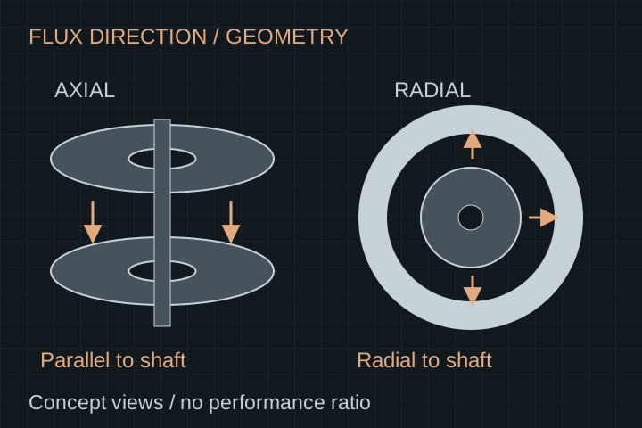
Axial and radial describe the main air-gap flux direction relative to the shaft. An axial machine uses disc-like active surfaces; a radial machine uses cylindrical active surfaces. Rotor and stator counts, excitation, slots, winding and cooling remain independent design choices.
Yokeless adds a narrower construction detail: a shared stator yoke is removed while individual magnetic teeth can remain. YASA describes a segmented-armature approach. An ironless active stator is another option, such as the patterned conductor concept described by Infinitum. Neither label makes all axial machines interchangeable.
| Label | What it identifies | What remains to check |
|---|---|---|
| Axial flux | Main working flux across disc faces, parallel to shaft axis | Core type, disc count, cooling, loads and ratings |
| Radial flux | Main working flux across a cylindrical gap, radial to shaft | Rotor arrangement, winding, cooling and package |
| Yokeless segmented armature | No common stator yoke; separate wound teeth may remain | Tooth material, support, winding and assembly details |
| Ironless active stator | No ferromagnetic teeth in the active winding region | Rotor back iron, conductor support, loss and control behavior |
2. Lock the comparison boundary before collecting numbers
Use the same shaft output points and the same allowed thermal conditions for both candidates. If one supplier quotes a cold-start peak and another a stabilized continuous point, a single kW/kg column hides the most important difference.
The table below is our proposed procurement method, not a published ranking. An unknown condition should remain unknown until clarified. Record measured, simulated and requested values in different fields. A simulation can help choose a prototype but is not the same evidence as an instrumented test.
| Comparison field | Record for each candidate | Reject this shortcut |
|---|---|---|
| Mechanical duty | Torque, rpm, duration, repetition and initial temperature | Comparing peak torque at one speed with power at another |
| Electrical conditions | Loaded bus window, phase RMS / peak current, inverter and control mode | Treating DC input current as winding phase current |
| Thermal boundary | Ambient, coolant inlet, flow, pressure and winding limit | Comparing an uncooled peak with a liquid-cooled continuous value |
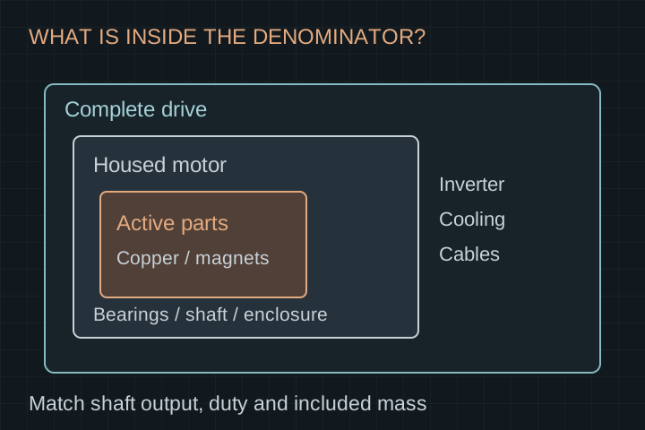
| Mass / volume | Included shaft, bearings, enclosure, feedback, cables and cooling hardware | Comparing active materials with a complete drive |
| Evidence status | Build revision, test method, instrumentation and uncertainty | Treating an attractive rendering or target as measured output |
3. Read torque and power at the same speed
Mechanical power is P = T × 2πn / 60, with torque T in Nm and speed n in rpm giving watts. The familiar rounded conversion is P(kW) = T(Nm) × n(rpm) / 9550. At zero speed, shaft power is zero even while the motor produces holding torque and generates heat.
Illustrative arithmetic: 200 Nm at 3,000 rpm is about 62.8 kW. It is not 200 kW. A hypothetical 20 kg housed motor at this point has 10 Nm/kg and 3.14 kW/kg. If its dedicated inverter and cooling auxiliaries add an assumed 10 kg, the corresponding complete-drive values become 6.67 Nm/kg and 2.09 kW/kg. No real model or thermal rating is implied.
The force lever arm is one reason disc geometry can be attractive. It does not establish a general scaling law for a purchasable motor: allowable diameter, loading, speed, stress, temperature and included hardware all constrain the result. Compare the actual candidates instead of converting a topology name into a density promise.
- Use shaft output rather than DC input power in output-density calculations.
- Pair every torque point with rpm, duration and thermal conditions.
- List included masses before calculating Nm/kg or kW/kg.
- Keep peak, continuous, simulation and measurement labels visible.
4. Compare heat rejection, not cooling labels
“Liquid cooled” does not specify the thermal resistance from winding to fluid. A jacket, a cooled stator support and direct-fluid contact have different interfaces. Ask where the hot spot is measured, which temperatures are inferred, and what flow and inlet temperature were used.
An independent EMRAX datasheet separates voltage variants and cooling-dependent output conditions, while its manual sets installation and operation requirements. Use that documentation style as a reminder to request conditions; do not transfer its numbers to another supplier. YASA also describes direct oil cooling for its own architecture, which does not prove all axial motors share that capability.
A concrete document check: the EMRAX 228 version 1.7 sheet says its motors require adequate airflow, including liquid-cooled installations, and warns against complete enclosure. Its front page also notes a product-generation transition. Confirm the exact model revision, installation instructions and available configuration before using a downloaded outline or rating in an integration decision.
| Question | Required record | Decision consequence |
|---|---|---|
| Continuous output? | Torque and rpm after agreed thermal stabilization | Can the sustained mission point be met? |
| Peak output? | Duration, initial state, repetition and cooldown | Can repeated transients be supported? |
| Cooling burden? | Fluid, inlet temperature, flow, pressure and auxiliary power | Can the vehicle or machine supply the loop? |
| Loss boundary? | Motor shaft output, electrical input and inverter inclusion | Are efficiency and rejected heat comparable? |
5. Review the assembly that holds the air gap
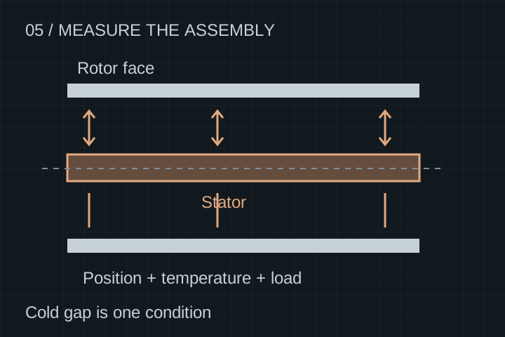
For a disc-shaped assembly, ask how the rotor faces, bearings, housing and stator carrier retain clearance over temperature and load. A nominally symmetric dual-rotor concept still needs a stiffness, tolerance and load review. Symmetry is not an inspection record.
Start with mounting datums, thrust and radial loads, speed limits and the controlled assembly revision. Request separate cold dimensional records and evidence appropriate to the hot or rotating condition. This is a proposed release workflow; the correct limits depend on the design and application.
- Identify bearing, housing, rotor retention and containment owners.
- State the maximum operating and transient speed.
- Agree balancing, runout and assembled-clearance methods.
- Define vibration, environment and system approval requirements separately.
6. Apply the method to three sourcing scenarios
These are decision scenarios, not customer case studies. Use them to identify the next evidence request rather than to predict a successful design. A candidate should leave the shortlist if it fails a hard system constraint, even when a headline density looks favorable.
| Scenario | Potential architecture reason | Evidence needed before selection |
|---|---|---|
| Axial length is tightly constrained; diameter has room | An axial package may fit the available envelope | Full housed dimensions, shaft interfaces, continuous map and cooling connections |
| Long, narrow installation; diameter is capped | Keep cylindrical radial candidates in the shortlist | Envelope fit, integrated mass, gearing and sustained output at the same duty |
| Low-speed precision positioning | Evaluate ironless and iron-cored options by disturbance limits | Separate unpowered detent, powered ripple, feedback and winding-temperature tests |
7. Compare the cost of the agreed deliverable
Separate engineering work, tooling, sample units, inspection fixtures, test reports and recurring units. Include the inverter, feedback, cables and cooling hardware only when they are inside the agreed scope. A frameless kit can shift integration work to your team rather than remove it.
For low-volume procurement, request drawing-release terms, change-control rules, sample acceptance and who owns production fixtures. No universal price premium or NRE saving can be concluded from flux direction alone.
- Use one interface specification for all quotations.
- Break out engineering, tooling, samples and recurring costs.
- Define who releases the motor, the drive and the final system.
- Keep timing and availability as supplier-confirmed fields.
8. What this guide can and cannot decide
This is a qualitative engineering and procurement framework, reviewed on 20 October 2026. Manufacturer sources establish their own topology descriptions and documentation practices. The examples and decision tables are our analysis, with explicitly assumed inputs; they are not cross-vendor dynamometer results.
No fixed efficiency, weight-saving or torque-density advantage is assigned to either topology. We have no matched YokelessMotor versus competitor test set to support one. The practical next step is to obtain candidate-specific evidence under a common brief and then decide whether prototype testing is justified.
- Prepare the duty, package and cooling boundary.
- Request a condition-complete candidate data set.
- Resolve missing evidence before ranking candidates.
- Use prototype results to support the final system decision.
SELECTION QUESTIONS
Questions engineers ask.
Are axial flux motors always more efficient?
No general efficiency ranking follows from flux direction. Compare losses over the required torque–speed cycle, temperature, inverter and cooling conditions. A peak efficiency at one point does not establish drive-cycle energy use.
Does a larger diameter always make an axial motor better?
A larger force radius can help torque generation, but available space, mechanical stress, speed, air-gap control and cooling constrain the complete design. Compare candidates within the actual envelope.
Are axial flux and yokeless the same?
No. Axial flux describes the main gap-flux direction. Yokeless describes removal of a shared stator yoke in a particular construction. Other axial arrangements retain a yoke or use an ironless active stator.
Can I compare peak kW/kg directly?
Only with matched output, speed, peak duration, initial temperature, cooling and included mass. Otherwise the ratio may compare different operating events and hardware boundaries.
Does a liquid-cooled motor have a fixed continuous-to-peak ratio?
No. Heat paths, coolant conditions, temperature limits and the load cycle determine the relationship. Request timed peak and continuous test conditions separately.
Can a frameless kit be compared with a housed motor?
It can be compared only after accounting for the housing, bearings, alignment, cooling and validation work missing from the kit. Keep component and system boundaries explicit.
Is a coreless axial design suitable for precision motion?
It is a candidate when tooth-related cogging is a concern. Powered ripple, low-inductance control, feedback, stiffness and thermal duty still need application-specific validation.
What should I send for an architecture review?
Send torque–speed duty, bus window, package and shaft loads, cooling conditions, environment, quantities and the intended deliverable. Start with non-confidential inputs and request an NDA before detailed CAD.
Primary sources and review scope.
Sources checked on 20 October 2026. External manufacturer descriptions apply to their own products. The analysis, decision tables and hypothetical examples in this guide do not constitute a YokelessMotor test report or a certification claim.
- YASA: axial flux technology
Segmented-armature / stator-yoke description and company-specific oil cooling. Vendor performance multipliers are not adopted here.
- Infinitum: PCB stator technology
Example of a distinct PCB active-stator approach; no equivalence with iron-cored yokeless motors.
- EMRAX 228 datasheet, version 1.7
Independent example of voltage variants and condition-dependent specifications; no borrowed motor rating.
- EMRAX user manual, version 1.7
Installation, cooling and operating-condition context; not evidence of our hardware capability.
TURN THE COMPARISON INTO A BRIEF
Bring the constraints that matter.
Start with non-confidential duty, package, quantities and acceptance requirements. Request an NDA before detailed drawings. The next step is a scoped feasibility discussion.
Discuss an architecture brief