
Specify every magnet vector
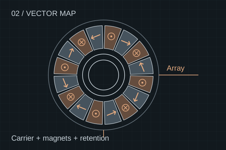
Supply polarity, magnetization direction, segment position and reference face. Distinguish a conventional alternating-pole axial rotor from a Halbach layout so assembly and field inspection use the same map.
CORE COMPONENTS / DRAWING-LED REVIEW
A Halbach rotor assembly inquiry needs a vector magnetization map, a mechanical retention concept and operating conditions. Review the magnet array, carrier and inspection package as one controlled assembly.
OEMs and R&D teams · Components or subassemblies · Scope confirmed after review
DESIGN TO MANUFACTURING
A high remanence label does not establish resistance to demagnetization in your operating load line. Likewise, adhesive selection alone does not qualify a rotor at speed. Establish temperature, fault current, retention, balance and containment assumptions before selecting the assembly process.
Supply polarity, magnetization direction, segment position and reference face. Distinguish a conventional alternating-pole axial rotor from a Halbach layout so assembly and field inspection use the same map.
Request grade-specific demagnetization curves at the operating temperature. Segment size, insulation between magnets, coating and field harmonics belong in the eddy-current and thermal review.
Agree carrier material, adhesive bond line, positive retention and shaft interfaces. Any carbon-fiber sleeve or cover requires its own stress, thermal and manufacturing review; it is not a universal overspeed solution.
DFM / SCOPE & COST DRIVERS
Define both the requirement and its acceptance record. Requested tests and equipment availability are confirmed for the project.
| Interface | Provide with the RFQ | Agree before release |
|---|---|---|
| Magnet array | Pole count, vector map, reference face and segment geometry. | Polarity/direction check and field-map measurement conditions. |
| Magnet material | Temperature envelope, load line and fault/demagnetization requirements. | Approved grade, coating, lot documents and allowable substitutions. |
| Carrier and retention | Speed envelope, inertia, axial force and retention concept. | Bond/fixture process, retention analysis and validation responsibility. |
| Mechanical interfaces | Datum scheme, bore/shaft connection, flatness and runout callouts. | Inspection fixture, assembled condition and dimensional report. |
| Balance and handling | Service speed, balancing planes and transport constraints. | Balance criterion, residual-unbalance record and safe handling plan. |
AGREE THE EVIDENCE
No published rotor here carries an approved maximum speed, flight qualification or guaranteed magnet grade. A quoted material designation must be supported by the selected supplier data. Export/material documentation is reviewed for the actual part and destination.
Air-gap metrology & quality gates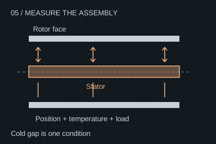
START WITH NON-CONFIDENTIAL INPUTS
Send the scope and operating envelope first. Request an NDA before sharing proprietary artwork or detailed CAD. The next step is scope clarification and feasibility review; pricing and timing follow the agreed deliverable.
ENGINEERING FAQ
No. Conventional alternating axial poles and Halbach-type direction patterns are different options. Supply the intended vector map; the layout name alone is not an assembly instruction.
Yes. Specify segment geometry, magnetization vectors, tolerances, coating, temperature requirements and lot documentation. Carrier machining and assembly can remain a separate scope.
No. A grade label by itself does not establish a safe operating temperature in the motor. Review grade-specific demagnetization curves, operating load line, fault fields and the complete thermal environment.
A component inquiry does not establish airworthiness. State the applicable qualification program, design authority, evidence and test responsibilities. Any flight-use approval remains program-specific.
RELATED COMPONENTS
Topology background from an independent motor manufacturer. Their results and manufacturing claims do not establish performance or affiliation for YokelessMotor. YASA: axial flux technology.
Published / reviewed 20 October 2026 · YokelessMotor engineering content · Illustrations and planning guidance, not measured production results. About the project.