
ENGINEERING RESOURCES / OEM DECISION GUIDE
Axial flux motor continuous vs peak power
An axial flux motor peak is useful only when its duration, starting temperature and repeatability match your load. Build a rating acceptance record before comparing kW.
By YokelessMotor · Published · Reviewed
THE ENGINEERING DECISION
Specify continuous operating points and timed overloads separately. Require the speed, bus, cooling boundary, initial state and recovery rule for each. A single peak-to-continuous multiplier cannot qualify repeated acceleration or a sustained propulsion duty.
See method and primary sourcesA point needs conditions
Pair torque and speed with duration, temperatures, cooling and electrical limits.
Recovery changes the answer
A cold-start overload does not establish a repeatable hot-cycle rating.
Compare the evidence
Keep requested, simulated and measured results in separate fields.
1. Replace one headline number with a rating record
An OEM specification should identify what must happen at the shaft, for how long and from what thermal state. Continuous output describes a sustained condition under stated boundaries. A timed overload describes a different condition; it must include an allowed duration and what happens before and after it.
As a document example, EMRAX 228 V1.7 separates an S2 30-second peak from S1 continuous columns and ties the columns to cooling conditions. That is evidence for this particular product document, not a universal 30-second definition of peak or a YokelessMotor rating.
ABB’s duty explainer describes S1 as constant load long enough to reach thermal equilibrium, and S2 as a limited run followed by de-energized rest sufficient to restore thermal equilibrium with the coolant. That distinction matters: an S2 label alone does not establish repeated hot-start operation. Ask the supplier to confirm the actual conditions and applicable duty designation; this guide does not certify compliance with an edition of a standard.
| Record | Continuous point | Timed overload |
|---|---|---|
| Shaft duty | Torque and rpm at each sustained point | Torque and rpm throughout the overload |
| Time rule | Agreed stabilization criterion and observation period | Duration, repetition interval and permitted event count |
| Initial state | Defined warm equilibrium or starting state | Cold start, hot start or measured pre-event temperatures |
| Cooling / environment | Ambient, fluid inlet, flow and mounting | Same recorded conditions, including changes during the event |
| Electrical boundary | Loaded DC bus, phase current convention and drive | Current ceiling, voltage limit and protective derating |
| Result status | Requested / simulated / measured, with revision | Measured event history and stop / recovery conditions |
2. Keep torque, power and speed together
Use shaft mechanical power P(kW) = T(Nm) × rpm / 9550, where 9550 is a rounded conversion. At zero speed, useful shaft power is zero even if the winding carries substantial current. A maximum torque and a maximum power listed on the same page need not occur at the same speed.
Hypothetical example: a request for 100 Nm at 3,000 rpm means approximately 31.4 kW at the shaft. A separate 200 Nm request at 1,000 rpm means about 20.9 kW. The second point has more torque but less mechanical power; neither arithmetic result defines a permissible duration or temperature.
| Requested point | Calculated shaft power | Still required |
|---|---|---|
| 100 Nm at 3,000 rpm | 31.4 kW | Continuous or timed status, cooling, losses and limits |
| 200 Nm at 1,000 rpm | 20.9 kW | Phase-current limit and permitted duration |
| Holding torque at 0 rpm | 0 kW mechanical | Holding current, heat path and time limit |
3. Define the continuous thermal boundary
maxon explains that winding temperature and the ability to reject losses bound continuous operation, with speed-related losses influencing the available torque. This supports a general review question: does the supplier provide the relevant operating region, rather than one torque value for every speed?
For acceptance, agree the temperature measurement locations, sensor calibration, inferred hot-spot method, allowed temperatures and a quantitative stabilization criterion. Do not invent a universal soak time. Include winding, rotor and other limiting parts, not only the most convenient external sensor.
The EMRAX manual provides a useful installation counterexample: even its liquid-cooled arrangement needs rotor air renewal, and hotter coolant can reduce continuous output. This manufacturer-specific detail illustrates why a cooling label alone cannot transfer a bench rating into an enclosed installation.
- Record ambient and inlet temperatures, flow, fluid and mounting throughout the run.
- Identify measured sensor temperature versus estimated hot-spot temperature.
- Agree a temperature-change limit over a specified observation window before calling the point stable.
- Record protection thresholds, derating and the actual achieved shaft point.
4. Use RMS current as a screen with explicit limits
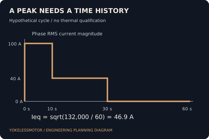
For piecewise constant phase RMS current magnitudes Ij over durations tj, the cycle-equivalent value is Ieq = sqrt(sum(Ij² × tj) / sum(tj)). With the same phase resistance, average three-phase copper loss is 3 × Rphase × Ieq². This is an algebraic copper-loss screen for balanced phases; it is not a complete thermal model.
Our hypothetical 60-second cycle uses 100 A for 10 s, 40 A for 20 s and zero current for 30 s. Ieq is about 46.9 A. The time-average current magnitude is only 30 A; using 30 A for heating would understate the copper-loss screen. Resistance varies with temperature, and speed-dependent, harmonic and mechanical losses are absent here.
The order of the intervals and the initial temperatures can change the hot spot even if Ieq is identical. A zero-current rotating interval may still generate losses. A measured limit on peak current, torque or mechanical stress also remains binding irrespective of a low average.
| Interval | Phase RMS magnitude | Time | I² × time |
|---|---|---|---|
| A: acceleration | 100 A | 10 s | 100,000 A²s |
| B: running | 40 A | 20 s | 32,000 A²s |
| C: zero-current assumption | 0 A | 30 s | 0 A²s |
| Full cycle | sqrt(132,000 / 60) = 46.9 A | 60 s | 132,000 A²s |
5. Ask what permits the next peak
Consider two hypothetical requests: one cold test with a long shutdown afterwards, and the same shaft overload repeated during a warm production shift. They can require different hardware even when peak kW matches. Ask for an event sequence rather than assuming the first successful pulse qualifies the second.
A timed overload test should state how the start condition is reached, what stops the event and how recovery is established. Loss of coolant flow, an already warm rotor or a drive current limit can invalidate a quoted duration. Define which conditions inhibit another event and how the controller reports that state.
| Scenario | Missing condition | Next evidence |
|---|---|---|
| Single cold-start demonstration | Applicability to a warm installation | Recorded initial and final temperatures plus cool-down history |
| Repeated warm accelerations | Accumulation and recovery at the worst duty | Instrumented repeated cycle with agreed acceptance and stop rules |
| Long high-speed coast between events | Rotor / core heating during low current | Speed-resolved losses and relevant temperatures |
6. Compare density only after agreeing the rating
Specific power is shaft output divided by the declared mass. A timed peak divided by active-part mass and a sustained point divided by a housed drive mass answer different questions. Record the included shaft, bearings, enclosure, inverter and cooling equipment before calculating a comparison.
For an aircraft concept, a heavier motor with a lighter cooling system may change the system result. For a marine installation, sustained heat rejection may govern instead. Those are engineering questions to evaluate with project evidence, not proof that one topology always wins.
- Use the same output duration and operating point.
- Use an identical mass and auxiliary-power boundary.
- Keep simulation and tested values distinct.
- Report unknown included masses before ranking candidates.
7. Release the rating against an evidence pack
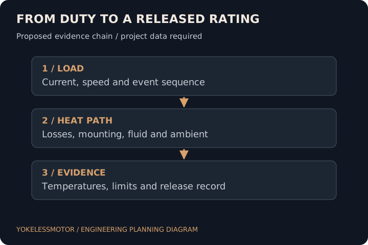
Use the downloadable record to send one common brief to every candidate. The acceptance owner should approve the method, instrumentation and decision limits before the prototype run. A plot without a test configuration or raw time history is difficult to audit.
For a component-only purchase, separate the supplier component checks from the integrator motor rating. A dimensional or winding inspection cannot establish continuous system output. For a complete motor, clarify which installation and inverter conditions remain the buyer’s responsibility.
| Evidence | Record before acceptance | Decision |
|---|---|---|
| Configuration | Serial / build revision, winding, drive software and sensors | Does the tested configuration match the offered build? |
| Measurement | Torque / speed / current / temperature channels, calibration and uncertainty | Can the claimed margin be resolved? |
| Run history | Initial state, full duty, coolant / ambient and protective actions | Were all conditions met throughout? |
| Release | Measured points, deviations and signed project decision | Accept, repeat or revise the specified scope |
8. Method and limits of this guide
Reviewed on 21 October 2026. Manufacturer documents support the thermal and rating distinctions identified above. The matrices, hypothetical cycles and acceptance method are our editorial engineering synthesis. They do not establish any YokelessMotor model rating or supplier qualification.
The next decision needs your load sequence, initial and limiting temperatures, installation and agreed verification plan. This page addresses rating semantics and acceptance; it does not replace a thermal model, a detailed duty-cycle design or an application-specific approval.
- OEM system engineer: define the complete load and cooling record.
- Supplier: identify the evidence status and remaining unknowns.
- Test owner: agree the measurement method and release rule.
SELECTION QUESTIONS
Questions engineers ask.
Does peak power always mean 30 seconds?
No. Duration is specific to the supplier, product revision and stated conditions. The EMRAX document example here labels a 30-second S2 point; it does not define peak for every motor.
Can I repeat a cold-start peak every minute?
Only if a defined repeated duty is supported by thermal and electrical evidence. The start state and recovery condition must permit each event.
Is continuous torque constant at every speed?
Do not assume so. Speed-related losses, voltage limits and heat rejection can change the permissible region. Request the operating envelope under your conditions.
Why is average current insufficient for heating?
Resistive heating depends on current squared. A cycle RMS screen captures that effect under its stated resistance and waveform assumptions; simple average magnitude does not.
Does RMS current prove the motor will stay cool?
No. It omits temperature dynamics, other losses, cooling variation and local hot spots. It also does not waive peak electrical or mechanical limits.
Is zero shaft power a zero-heat condition?
No. Holding torque can require current at zero speed. A rotating zero-current interval can still involve magnetic and mechanical losses.
Can peak torque and maximum power occur together?
They may refer to different operating points. Pair torque with rpm and duration before using the mechanical-power equation.
What establishes thermal stabilization?
The project test plan should specify sensor locations and a temperature-change criterion over an observation period. This guide does not assign a universal time or threshold.
Does liquid cooling guarantee a continuous rating?
No. Fluid inlet, flow, mounting, air renewal and the complete heat path matter. Confirm the offered installation matches the evidence.
How should I compare power density?
Use matched shaft duty, duration, cooling and included mass. Keep active materials, housed motor and complete-drive boundaries separate.
Can component inspection validate a complete motor rating?
No. It validates the agreed component characteristics. The complete assembly still needs its own electrical, mechanical and thermal evidence.
What should I send for a rating review?
Send a non-confidential load sequence, speed, bus window, initial temperatures, cooling, envelope, quantities and acceptance goals. Request an NDA before proprietary drawings.
Primary sources and review scope.
Sources checked on 21 October 2026. External manufacturer descriptions apply to their own products. The analysis, decision tables and hypothetical examples in this guide do not constitute a YokelessMotor test report or a certification claim.
- EMRAX 228 datasheet V1.7, table on PDF page 2
Example of explicitly timed S2 output, S1 output, cooling-dependent columns and winding variants. Applies to this manufacturer and revision only; not our specifications.
- maxon: continuous operating range of BLDC motors
Explains the winding-temperature and heat-rejection boundary and why speed-related losses change continuous torque. Its example temperature is not a general motor limit.
- EMRAX installation and maintenance manual V1.7, pp. 16–17
Manufacturer-specific airflow, cooling installation and inlet-temperature conditions. Demonstrates why an installation boundary belongs in a rating request.
- ABB Technical Application Papers No. 7, Annex D, printed p. 35
Motor-duty terminology: S1 equilibrium and S2 run/rest distinction. This explanatory document is not evidence of compliance or a substitute for the applicable project standard edition.
TURN THE COMPARISON INTO A BRIEF
Bring the constraints that matter.
Start with non-confidential duty, package, quantities and acceptance requirements. Request an NDA before detailed drawings. The next step is a scoped feasibility discussion.
Discuss a motor rating brief