CUSTOM MOTOR DEVELOPMENT / OEM & R&D

Ironless axial flux motors. Engineer the motion quality.

A distinct topology / application-led development

For precision-motion OEMs and research teams evaluating an ironless active winding, start with the allowable disturbance torque and thermal duty. Removing stator teeth changes the magnetic circuit, conductor support and drive requirements; it does not eliminate every source of torque ripple.

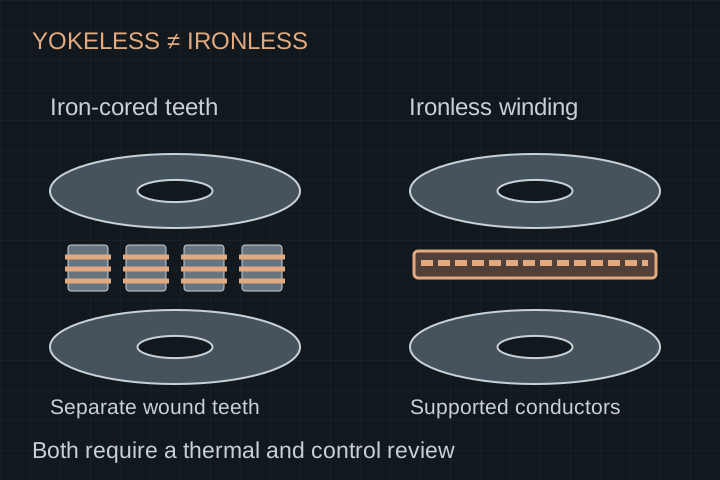
Section comparison between an iron-cored yokeless segmented stator and an ironless supported winding, both between rotor discs
Topology comparison, not a production drawing. Ironless describes the active stator winding region; rotor back iron may remain. Yokeless alone does not mean ironless.

THE PROGRAM STARTS HERE

Resolve the constraints that change the design.

01

Cogging versus powered ripple

Removing ferromagnetic stator teeth removes that tooth-interaction cogging mechanism. Commutation, current ripple, magnetic harmonics, sensor error and bearings still affect motion. Specify unpowered detent and powered ripple tests separately.

02

Conductor support is a thermal design

A wound air-core stator and an etched PCB stator need different fabrication inputs. Review conductor loss, insulation, potting, stiffness and the complete path to the cooling boundary.

03

Low inductance needs a drive review

Request winding resistance and inductance definitions, current-loop behavior and measured PWM ripple. The inverter, switching strategy and any filtering need to match the actual winding.

INPUTS / INTERFACES / OWNERSHIP

Build a usable operating envelope.

These are the decisions to scope before a quotation. Feasibility, engineering deliverables, sample cost, tooling and recurring production terms follow the agreed requirements.

Iron-cored yokeless and ironless stator decisions
DecisionIron-cored yokelessIronless active stator
Active statorSegmented ferromagnetic teeth and coils; no common stator yokeSupported copper winding or PCB traces; no active ferromagnetic teeth
Magnetic circuitCore permeability and saturation enter the designEffective nonmagnetic gap includes winding and support thickness
Motion qualityCogging and powered ripple require design and measurementTooth cogging mechanism removed; powered ripple still requires measurement
Thermal pathCoil insulation, core / potting and cooling interfacesConductor, support / resin / laminate and cooling interfaces
Drive reviewConstants and current limits matched to the designInductance, PWM ripple and sensing especially relevant
Procurement scopeCore, wound segments, kit or housed assemblyWound stator or PCB fabrication, rotor–stator kit or motor program

WORKED EXAMPLE / ASSUMED INPUTS

Separate the copper-loss question from “zero cogging”

Illustrative balanced three-phase winding: at 10 A phase RMS and 0.20 Ω resistance per phase at the stated temperature, DC-resistance copper loss is 60 W. At 20 A it becomes 240 W if resistance is held constant. Removing a stator core does not remove this heat.

P_copper = 3 × I_phase,RMS² × R_phase

Arithmetic example only, with wye-connected phase definitions. Actual resistance rises with winding temperature; AC conductor effects and inverter ripple add loss. These are not measured losses or a motor rating.

Download motor brief worksheet

APPLICATION-SPECIFIC DUTY

Bring the load case behind the power number.

Precision positioning

Provide low-speed torque, encoder resolution, allowable ripple and disturbance bandwidth. Measure torque at the shaft with a defined controller configuration rather than relying on the topology label.

Medical-device development

Specify the mechanical duty, noise, temperature and cleaning environment. Device qualification, traceability and validation requirements must be agreed with the responsible manufacturer.

Research & specialized gimbals

Define inertia, reversal duty, cable routing and thermal paths. Space-environment or vacuum use adds separate material, heat-rejection and qualification work; no flight heritage is claimed.

AGREE ACCEPTANCE BEFORE SAMPLES

Request the evidence for your operating point.

  • Unpowered detent torque measured separately from powered torque ripple, with speed and bandwidth stated.
  • Phase resistance, inductance and back-EMF with winding connection, temperature and test conditions.
  • A thermal duty test including the actual support / potting / cooling arrangement.
  • Controller compatibility, feedback error, current ripple and tuning records.
  • Dimensional stability, rotor clearance, balance and assembly release responsibilities.
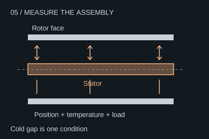
Review inspection and release gates
Separate rotor-to-stator clearances measured across an assembly at defined positions
Cold component dimensions do not establish hot, loaded assembly clearance. Agree the build, conditions, inspection methods and release owner.

START WITH A NON-CONFIDENTIAL BRIEF

Discuss your coreless & ironless axial programs.

Send the requirements and quantities first. Request an NDA before sharing detailed proprietary CAD. The review defines feasibility, deliverables and responsibilities before pricing or timing is confirmed.

  • Continuous torque, speed range and reversal / holding cycle
  • Allowable detent torque and powered torque ripple with measurement bandwidth
  • Package, inertia, shaft and mounting constraints
  • Cooling path, ambient and winding temperature limit
  • Inverter, feedback, winding or PCB preference and quantities

Start your engineering brief.

Use the inquiry form, or contact us directly with your duty cycle, package, cooling and quantity requirements.

ENGINEERING & PROCUREMENT

Questions before a motor RFQ.

Are all yokeless motors coreless?

No. A yokeless segmented-armature motor can retain ferromagnetic stator teeth while removing the shared stator yoke. An ironless active stator removes those teeth. They are different magnetic and thermal designs.

Does ironless mean there is no iron anywhere?

Not necessarily. The term here refers to the active stator winding region. Rotor back iron or other magnetic support structures may remain, so the complete cross-section must be reviewed.

Can you guarantee zero torque ripple?

No generic zero-ripple guarantee is made. Eliminating stator-tooth cogging does not eliminate current ripple, commutation harmonics, sensor error or mechanical disturbances. Agree separate detent and powered tests.

Is a PCB stator the only coreless option?

No. A supported air-core wire winding is another approach. PCB artwork, layer stack and vias differ from wire, insulation, winding fixtures and potting; quote and validate each process separately.

Can an existing inverter drive an ironless winding?

Compatibility is not automatic. Review winding inductance, current measurement, switching strategy, control bandwidth, feedback and heating under the intended operating cycle.

Is a STEP model or specification sheet available?

No released motor model or approved dimensional file is offered on this page. Share the package requirements first. Any later interface drawing must carry its own revision, units and use limitations.

Continue your engineering review.

Engineering resources and selection guides

Connect this scope to your application.